I love the old 0-6-0 and 0-4-0 switchers with their slope back tenders. There was the 0-4-0 engines with their short slope back tenders and the 0-6-0 engines some with short slope back tenders and the top line 0-6-0 with their long slope back tenders.
Over the years many of the tenders and connections were switched by owners It is confusing. I am trying to list here how they were offered.
Magic Electrol
Magic Electrol had a small relay that activates from the "horn" button. It required another, or 3rd wire from the engine. When activated it would ground the E unit causing it to cycle. To use the Magic Electrol correctly, the E-unit switch on the engine was in the "off" position.
201, 232, 233 and 1663 engines and tenders had Magic Electrol
These engines also had a wire that connected the front coupler on the engine to the rear coupler and 5th rail pickup.
Teledyne
Pushing the whistle/bell will also cause the engine and tender to uncouple, anywhere on the track. This used a small relay in the tender, but in this case it connected 3rd rail power. It was connected into the 5th rail wire for the coupler that also went to the engine.
1663, 227 and 228 engines and tenders came with Teledyne relays.
Postwar engines that can have Teledyne added
There are electronic versions of the Teledyne relay now available. Some are configured to work on Bell or Whistle. The requirement is the engine and tender if used have coil couplers and no whistle/horn.
Cast Engine for 0-4-0
Some of the O-4-0 engines came with a cast engine frame. They are noted below. It mounted with the slot in the front and a Screw hole in the back. The Prewar 229 also used this engine, but it did not have a tapped mounting hole in the back. Also the wiring to the E-unit on these was a little different. One brush had a ground to the casting and the other an E-unit wire. 2 Wires from the E-unit went to the field. The field switched polarity when the E-unit cycled, not the armature.
The Cast Engine frame and motor, front to the left.
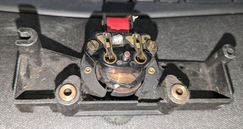
2 or 3 Plug connectors
These engines had 2 plugs in the back of the engine. The left side of the engine for engine coupler connection. The middle for power to the tender on Prewar locos. On postwar locos the middle was a ground. These worked with tenders with or without a Teledyne relay.
There was an optional 3rd, right, plug. This was on engines with Magic Electrol connections. It connected to the E-unit relay wiring ground. It needed a matching Tender with 3 wires an a Magic Electrol Relay.
Prewar 3 plug connection with Magic Electrol. Middle plug is power.
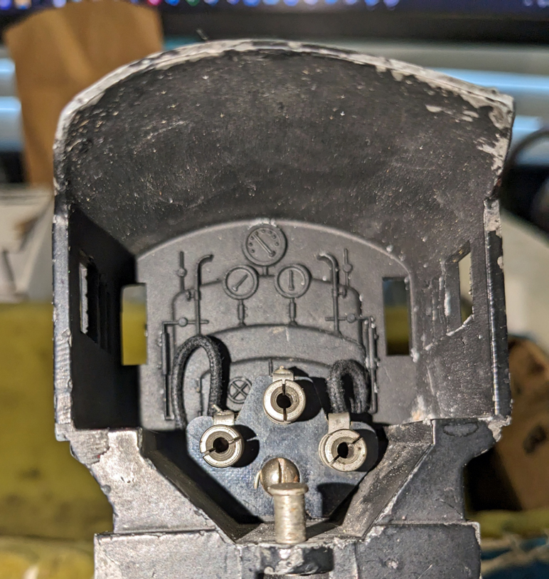
This is a postwar 2 plug. The middle is grounded.

The Prewar engines with a short slope back tender.
All had a left wire connecting the 5th rail pickup from the tender to the engine for front/rear coupler activation. These engines had a post for connecting the tender. All had a front light.
Short slope back tenders
On these tenders an RCS track could be used to run the coupler on both the tender and the engine from the 5th rail pickup in the tender. All had a backup light that was not directional and a cast metal shell. They did not have a center rail pickup and used a power wire from the engine to get 3rd rail power.
2201, 2203 and 1663 tenders could have metal or plastic coal pile
Prewar 0-6-0 engines with Long slope back tenders.
All had a wire connecting the 5th rail pickup from the tender to the engine for front/rear coupler activation. All had a horizontal engine with roller pickups similar to the 700e/763E. All had a front light and a post to connect the tender.
For repair of the 227, 228 and 230-233 engines see the 228 repair notes. These engines are similar except for front coupler height. the front boiler number and the number of plug ins on the motor brush plate.
Long slope back tenders
On these tenders an RCS track could be used to run the coupler on both the tender and the engine from the 5th rail pickup on the tender. All had 4 wheel trucks, a cast metal shell a non directional backup light. These did have a center rail roller pickup that helps the engine power through switches.
Wires to engine are Left, front coupler, middle power, and an optional 3rd wire for Magic Electrol.
Prewar with 0-6-0 Scale couplers
Postwar engines with a bell ringing tender.
These engines are 0-4-0 configuration. Some had 2 plug ins. Left plug, engine coupler, middle plug Ground. All had a front light and a draw bar to connect the tender.
Tenders. These are all short slope back tenders.
Notable things
The prewar 1662 and 1663 engines do not run through postwar switches and some control switches with the magnets well. The wheel diameter is slightly smaller causing the flanges to bottom out and bump through switches. The smaller diameter wheel also causes the geared wheels to bump at the magnets on postwar controller tracks. A workaround for this is to use an engine from a 1656, or switch out the drive wheels with drive wheels from a 229 engine that uses a similar cast motor.
The 1665 may also have problems bumping on the magnet area of a postwar controller track. The controller tracks with magnets where not made until a couple of years after the 1665's production. It is the gear on the inner wheel that catches. Carefully trimming the overhanging plastic at the top of the magnet may help eliminate the problem. Don't cut into the coil!
The prewar 1662, 1663, 201 and 203 had a Power plug for the middle plugin. Their tenders did not have a 3rd rail pickup. The postwar 1656 and 1665 had a ground connection for the middle plug. Their tenders had a 3rd rail pickup. Many owners switched it to a power plug in the engine and connected the wire in the tender to the 3rd rail pickup. To better to get through switches. No matter, always check to see if the center plug on the engine is ground or power. 0 ohms to ground vs. 0 ohms to 3rd rail.
The plugins on the 227, 228 and 230-233 engines may be a hole in the brush plate or may have standoffs for the plugin. Initially it was a hole and later production the standoffs were added.
See Bell
Ringing Tender Repair for details on the Bell Ringing mechanism.
Last Update Jan 24 2026