
Notes on the MMU3
My various implementations of the
Prusa MMU3
Last Update April 26, 2026
I started with an MMU2 and had many mods to make it reliable with the MK3s. Then came the MMU3 upgrade and my upgrade to the MK4s. Currently the MMU3 is mounted to a Core One. Notes on the first, MK4s, and second, the Core One implementation are listed below.
Changes to the MMU3 vs MMU2 Updated 5/2/2024
The MMU3 vs the MMU2 works much better. MK4s and MMU3 work
together as a single machine.
The changes to the MMU3 vs. MMU2 improve reliability, filament flow, sensor function and software interface. It seems to cover the majority of pain points I had with the original MMU2. All the printed parts changed. The 2 mount feet for the MMU2 could be used on the MK3S+, but the MK3.9/4 will need the new mount feet. I upgrade the MMU2 to the MMU3 using version 4 of the MMU3 parts.
The MMU option must be enabled in the MK4/MK3.9/Core One settings. What isn't mentioned currently there is also a "Cutter" setting to enable. This enables "Forming" the tip. I turned it on at the start. Hopefully Prusa will document that somewhere.
Buffer changes
MMU3 Nextruder changes for MK3.5, MK3.9, MK4, MK4S and Core One.
I think all these changes should be in All Nextruder assemblies.
What makes the best MMU3 setup?
I have tried multiple styles of spool holders, buffers, re-winders and orientations. Most re-winders take up too much room or have problems if they are not designed for the exact retract length needed. All the "printed" clutch systems I tried were unreliable. A good feeder to the MMU3 must follows these rules.
In used a dry box with rollers, the Prusa MMU3 buffer and a high, rear entry into the enclosure to feed the MMU3. It worked for over a year, but the length of the tubing is still excessive in my opinion. I tried to meet all the rules. I used a slot for the PTFE tubes going into the enclosure so the tubes would flex and not have a tight turn. The only thing that could make this better would be to have a dry box big enough to put the buffer in.
The evolution of the MMU3, Dry box, buffer and re-winder systems
over many years. See my
Dry box notes.
Method #1. Tube entry into the enclosure. High to reduce the bends and a slot to allow flex and adjustment in the tubes. My need to access the back of the MMU has been reduced with the MMU3 changes.
Method #2 The entry into the enclosure from the back of the enclosure. Holes high to align with the MMU3. The tubes go in straight to the MMU. No more binding/bending before entering the MMU3. Works great with the Horizontal mounted MMU3. Tubes do not interfere with the print volume.

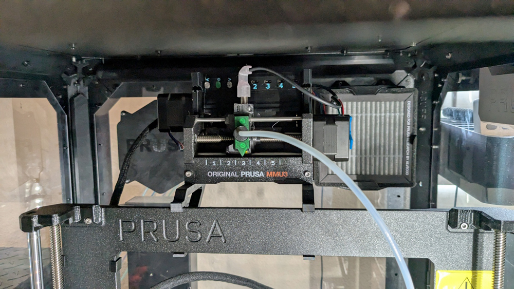
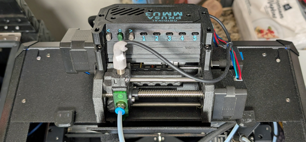
The MMU3 on a horizontal mount on the MK3/4 series. I like it horizontal for access in the back, but you must also consider the ptfe tube clearance on tall prints. It also allows you to use the full print volume with the MMU. Before the tubes could interfere with the print volume.
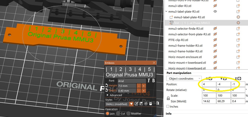
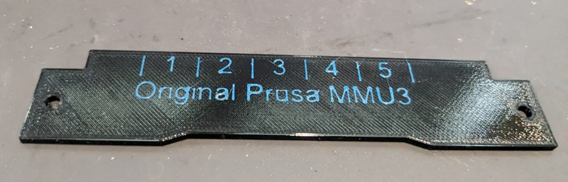
My print of the name plate.
When I moved the MMU3 to the Core One I used the enclosed conversion method. I used the MMU3 mount as designed. It seems to be working well. You do loose the number board on the bottom, but it can not be seen from the top. I did add one sliding cover mod to help keep heat in when needed.
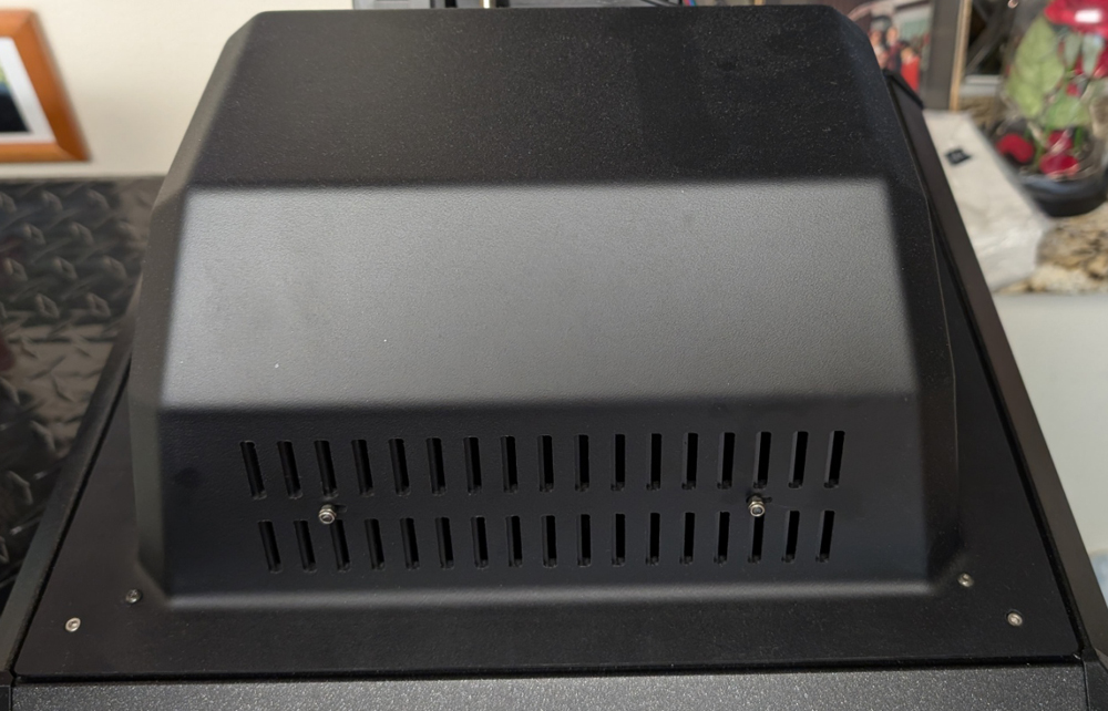
MMU3 with Cover Removed.

I found the auto-ventilation grill control for the MMU on the Core One useful also. It works once the code is applied. See Vhubbard make notes on the page.
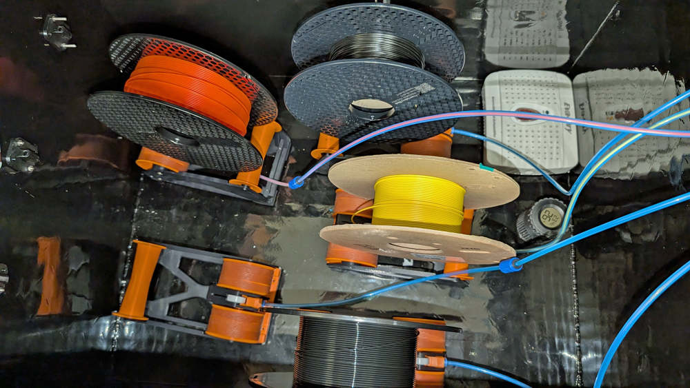
When moving to the Core One, I removed the buffer and implemented the Filamentalist Classic Re winder. This uses a metal one way clutch system, not a printed clutch. It helps rewind the spool when filament is back fed. When normal feeding it free wheels. I added rubber feet to help them not slide on the metal floor. I put them in the Dry box. This shortened the tubing and reduced drag overall without the buffer. They have been working well.
Filament tip for the MMU
When the MMU uses up a spool, the end of the filament must be a straight piece of filament. Some providers put a hook on the filament to help in winding. The hooks cause jams in the MMU3 end of filament unload process. Cut the hooks off when at the end of the spool before they go to the MMU. Some spool providers have corrected this.
Future of the MMU
What is the future of the MMU? Something different and most likely proprietary. Why? It isn't simple or cheap to design, test and prove out new systems. Especially in an open system. Crowd labor works for simpler projects, but larger more technical projects need dedicated development teams with good development tools, programming standards and long term support ability. These company systems are often patented.
The next Multi Material system for Prusa will be the INDX from Bondtech. Why? Size to
need, 2-7 or more. Simplified loading, no buffer/re-winder
needed. Filament only goes through a single feed unit, not a 2nd as
with the MMU. Fast heating with induction heating. Large time
savings when switching filament. Evolution from a hobby to a more
reliable tool. A big dry box
will still be needed.
Back to My 3D Printing